|
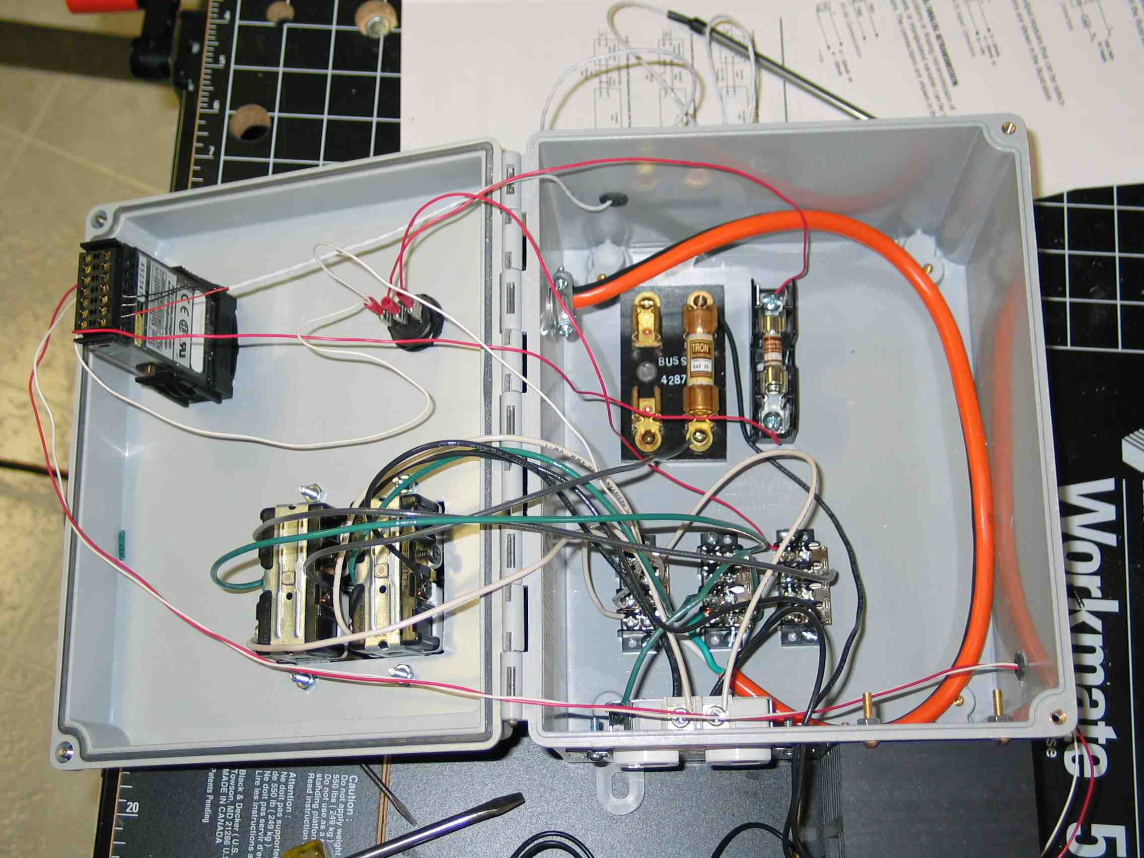
Building the electric portion of the RIMS system was a bit nerve wracking. The PID controller cost $159, and I was worried that I was going to fry it. However, the manual was pretty clear, although it took me a little while to figure out that I needed to download it from Omega -- they didn't send a hard copy. Click the thumbnails to enlarge. Note that they are pretty big and might take a while to load depending on the speed of your connection. The bottom of the control box is on the left of this picture. 110 volts
comes in through the orange cable. This is wired to three terminal jacks
(hot, neutral, ground), near the outlet on the bottom of the picture. All
of the AC comes from these terminal jacks. The pump wiring is simple, only
to the switch toward the middle of the picture, then to the
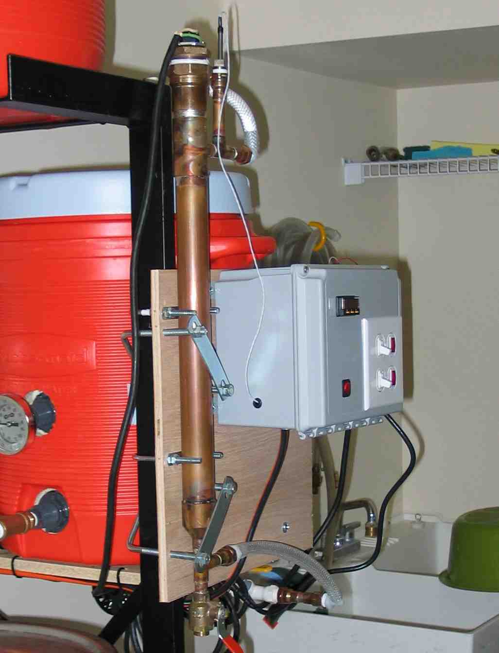
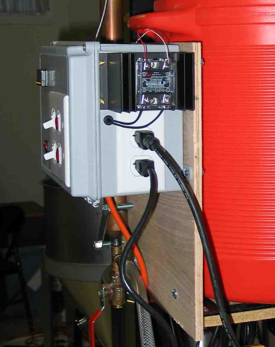
The PID controller, top left, is powered through the small switch near the top, through a 1A fuse (the small one), then to the controller. The input to the controller are the three wires from the RTD temperature probe (seen near the top of the photo on some papers), and output goes out the grommet on the bottom right of the photo, to a solid state relay (SSR -- bottom right of the photo, barely seen). The SSR is a switch which is controlled by the temperature controller. The input to the high voltage side of the SSR is run through a switch, then through a 25A fuse (the large one), then to the outlet on the right side. Note that the outlet was split so that each plug supports a separate circuit. The circuit can be seen in this diagram -- thanks to Carlos in Mexico City for drawing it for me. The PID controller has a surprisingly rich user interface. But during normal use, you simply configure a "set point" which is the temperature it is trying to reach, and the display shows what the temperature is. While the current temp is very low compared to the set point, the SSR is switched on all the time. As the temp gets close, the on cycle gets shorter and shorter, until the set point is reached. Here are a couple of views of the controller mounted on the brewery stand.
DISCLAIMER: While I hope you find this site interesting and useful for reference purposes, I am neither a plumber nor an electrician, and therefore cannot take any liability for any injury which may occur through implementation of any apparatus which is based on the information contained herein. Please feel free to use this information at your own risk. [ Back Home]
Send suggestions or comments to lou@lousbrews.info.
|